ADC (Analog To Digital Converter) adalah pengubah
input analog menjadi kode – kode digital. ADC banyak digunakan sebagai pengatur
proses industri, komunikasi digital dan rangkaian pengukuran/pengujian. Umumnya
ADC digunakan sebagai perantara antara sensor yang kebanyakam kebanyakan analog
dengan sistim komputer seperti sensor suhu, cahaya,
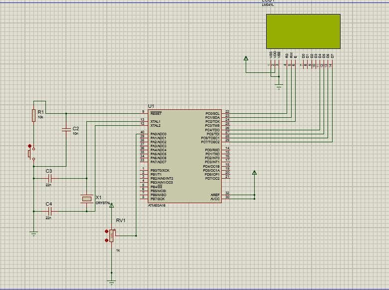
tekanan/berat, aliran dan sebagainya kemudian diukur dengan menggunakan sistim
digital (komputer). Berikut simulasi ADC menggunakan PROTEUS DAN CVAVR :
/*****************************************************
This program was produced by the
CodeWizardAVR V2.05.3 Standard
Automatic Program Generator
© Copyright 1998-2011 Pavel Haiduc, HP
InfoTech s.r.l.
http://www.hpinfotech.com
Project :
Version :
Date
: 18/05/2017
Author
: DEFAUL
Company :
Comments:
Chip type : ATmega16
Program type : Application
AVR Core Clock frequency: 16,000000 MHz
Memory model : Small
External RAM size : 0
Data Stack size : 256
*****************************************************/
#include <mega16.h>
#include <delay.h>
#include <stdio.h>
// Alphanumeric LCD functions
#include <alcd.h>
#define ADC_VREF_TYPE 0x00
// Read the AD conversion result
unsigned int read_adc(unsigned char
adc_input)
{
ADMUX=adc_input | (ADC_VREF_TYPE &
0xff);
// Delay needed for the stabilization of
the ADC input voltage
delay_us(10);
// Start the AD conversion
ADCSRA|=0x40;
// Wait for the AD conversion to complete
while ((ADCSRA & 0x10)==0);
ADCSRA|=0x10;
return ADCW;
}
unsigned int hasiladc;
unsigned char lcd[16];
void main(void)
{
// Declare your local variables here
// Input/Output Ports initialization
// Port A initialization
// Func7=In Func6=In Func5=In Func4=In
Func3=In Func2=In Func1=In Func0=In
// State7=T State6=T State5=T State4=T
State3=T State2=T State1=T State0=T
PORTA=0x00;
DDRA=0x00;
// Port B initialization
// Func7=In Func6=In Func5=In Func4=In
Func3=In Func2=In Func1=In Func0=In
// State7=T State6=T State5=T State4=T
State3=T State2=T State1=T State0=T
PORTB=0x00;
DDRB=0x00;
// Port C initialization
// Func7=In Func6=In Func5=In Func4=In
Func3=In Func2=In Func1=In Func0=In
// State7=T State6=T State5=T State4=T
State3=T State2=T State1=T State0=T
PORTC=0x00;
DDRC=0x00;
// Port D initialization
// Func7=In Func6=In Func5=In Func4=In
Func3=In Func2=In Func1=In Func0=In
// State7=T State6=T State5=T State4=T
State3=T State2=T State1=T State0=T
PORTD=0x00;
DDRD=0x00;
// Timer/Counter 0 initialization
// Clock source: System Clock
// Clock value: Timer 0 Stopped
// Mode: Normal top=0xFF
// OC0 output: Disconnected
TCCR0=0x00;
TCNT0=0x00;
OCR0=0x00;
// Timer/Counter 1 initialization
// Clock source: System Clock
// Clock value: Timer1 Stopped
// Mode: Normal top=0xFFFF
// OC1A output: Discon.
// OC1B output: Discon.
// Noise Canceler: Off
// Input Capture on Falling Edge
// Timer1 Overflow Interrupt: Off
// Input Capture Interrupt: Off
// Compare A Match Interrupt: Off
// Compare B Match Interrupt: Off
TCCR1A=0x00;
TCCR1B=0x00;
TCNT1H=0x00;
TCNT1L=0x00;
ICR1H=0x00;
ICR1L=0x00;
OCR1AH=0x00;
OCR1AL=0x00;
OCR1BH=0x00;
OCR1BL=0x00;
// Timer/Counter 2 initialization
// Clock source: System Clock
// Clock value: Timer2 Stopped
// Mode: Normal top=0xFF
// OC2 output: Disconnected
ASSR=0x00;
TCCR2=0x00;
TCNT2=0x00;
OCR2=0x00;
// External Interrupt(s) initialization
// INT0: Off
// INT1: Off
// INT2: Off
MCUCR=0x00;
MCUCSR=0x00;
// Timer(s)/Counter(s) Interrupt(s)
initialization
TIMSK=0x00;
// USART initialization
// USART disabled
UCSRB=0x00;
// Analog Comparator initialization
// Analog Comparator: Off
// Analog Comparator Input Capture by
Timer/Counter 1: Off
ACSR=0x80;
SFIOR=0x00;
// ADC initialization
// ADC Clock frequency: 500,000 kHz
// ADC Voltage Reference: AREF pin
// ADC Auto Trigger Source: ADC Stopped
ADMUX=ADC_VREF_TYPE & 0xff;
ADCSRA=0x85;
// SPI initialization
// SPI disabled
SPCR=0x00;
// TWI initialization
// TWI disabled
TWCR=0x00;
// Alphanumeric LCD initialization
// Connections are specified in the
// Project|Configure|C
Compiler|Libraries|Alphanumeric LCD menu:
// RS - PORTC Bit 0
// RD - PORTC Bit 1
// EN - PORTC Bit 2
// D4 - PORTC Bit 4
// D5 - PORTC Bit 5
// D6 - PORTC Bit 6
// D7 - PORTC Bit 7
// Characters/line: 8
lcd_init(8);
while (1)
{
hasiladc=read_adc(0);
lcd_gotoxy(0,0);
sprintf(lcd,"Hasil ADC: %d",read_adc(0));
lcd_puts(lcd);
delay_ms(10);
lcd_clear();
}
}
Komentar
Posting Komentar